The word tolerance is frequently spoken while deciding on a manufacturer for your sheet metal components. Everyone wants their parts to be exact reproductions of their models, but in reality, perfection can never be defined with absolute certainty. We all refer to that variation as tolerance. Although the phrase "manufacturing tolerances" is frequently used, the reality might vary greatly depending on the technique in issue. This article compares the effects of feasible tolerances on machining, 3D printing, and sheet metal operations.
Machining, sheet metal fabrication, and 3D printing
Both machining and 3D printing are extremely exact manufacturing processes that precisely remove or add material to create a final geometry. A final geometry is created by cutting, bending, and stretching thin sheets of metal in sheet metal, a significantly less exact manufacturing technique. The sheet metal method's lower tolerances are a result of the very variable methods utilized to create a geometry.
Manufacturing tolerances are best understood in the context of machining. On sheet metal prints we frequently encounter machining tolerance blocks.
In engineering school, they teach that ±0.005 in. (0.127mm) for three significant figures is the baseline tolerance. This is possible because there is one machine creating features irrespective of features already created. It doesn’t matter if you drilled a hole in one place, the next hole position and size will be determined solely by the machine making the cut.
Although the exact degree of precision depends on the materials and procedures employed, 3D printing is also a precise manufacturing technique. Just like with machining, keep in mind that while using 3D printing, new features are added to a part independent of existing ones. It will continue to maintain a high degree of precision and add material where it is required (assuming your design properly supports the part during manufacturing).
In a way, sheet metal straddles the boundary between manufactured things and handcrafted items. To create the final geometry, we stretch and bend the material. With a single, incredibly precise machine, we are not adding and subtracting metal. In fact, depending on the features needed, sheet metal fabrication calls for close to a dozen machines. A cutting machine and a bending machine, each with their own tolerances and restrictions, are needed to create even the most basic formed part.
Our Sheet Metal Tolerances
Protolabs Sheet Metal Tolerances:
- Tolerances on one surface
- Tolerances across multiple surfaces
As compared to tolerances across numerous surfaces, those on a single surface are substantially tighter. When examining a single surface, a laser or punch is typically used to create the majority of the features. We can hold tighter tolerances thanks to technology, much like with machining and 3D printing. Things get a little less clear when we add bends to the geometry.
Tolerances on One Surface
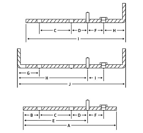
Refer to the table below for standard tolerances for each marked section of the part.
|
Feature Reference Tolerance +/- |
|
Edge to Edge A 0.005 in. (0.13mm) |
|
Edge to Hole B 0.005 in. (0.13mm) |
|
Hole to Hole C 0.005 in. (0.13mm) |
|
Hole to Hardware* D 0.010 in. (0.25mm) |
|
Edge to Hardware* E 0.010 in. (0.25mm) |
|
Hardware to Hardware* F 0.015 in. (0.38mm) |
|
Bend to Hole G 0.015 in. (0.38mm) |
|
Bend to Hardware* H 0.015 in. (0.38mm) |
|
Bend to Edge I 0.010 in. (0.25mm) |
|
Bend to Bend J 0.015 in. (0.38mm) |
Studs, nuts, standoffs, and other self-fastening products are regarded as hardware*.
Tolerances on Multiple Surfaces
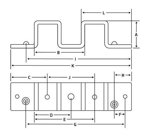
For standard tolerances for each designated section of the part, please see the table below.
| Feature Reference Tolerance +/- |
| Bend to Bend A 0.015 in. (0.38mm) |
| Bend to Bend B 0.030 in. (0.76mm)* |
| Edge to Hole C 0.015 in. (0.38mm) |
| Bend to Hole D 0.030 in. (0.76mm)* |
| Bend to Hole E 0.030 in. (0.76mm)* |
| Hole to Formed Feature F 0.010 in. (0.25mm) |
| Hole to Formed Feature G 0.030 in. (0.76mm)* |
| Edge to Formed Feature H 0.010 in. (0.25mm) |
| Edge to Formed Feature I 0.030 in. (0.76mm)* |
| Hole to Hole J 0.020 in. (0.50mm)* |
| Edge to Edge K 0.030 in. (0.76mm)* |
| Edge to Bend L 0.030 in. (0.76mm)* |
*Non-cumulative.
The Stacking Struggle
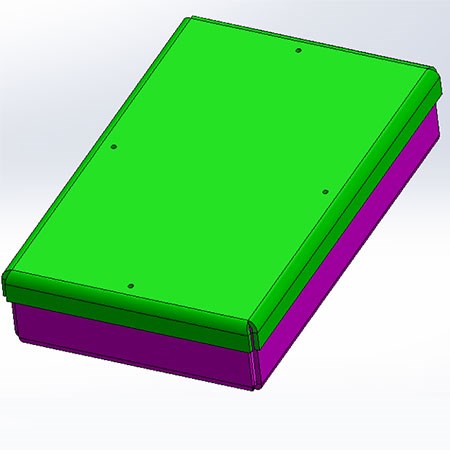
Let's utilize this box and lid as a case study for sheet metal tolerances. This will enable us to examine how fabrication of sheet metal affects the tolerancing that may be achieved. The simplicity of this assembly is misleading. Consider the subtleties involved in developing quality sheet metal parts as we delve deeper into the design.
Take a peek at the green lid first. Four flanges are created from the middle segment of this component. Four holes in this central part are used to attach the lid to the pink box below it. These four holes are created by a laser, and a computer-controlled procedure closely regulates their position and size. The location of these holes will be exact and unaffected by the bend angle and linear tolerances in the vicinity.

The situation with the holes in our pink box is a little different. The holes on the box are spread across four different surfaces, each spaced by four bends, as opposed to the lid's holes, which are all on the same surface. We get a linear tolerance of 0.030 in. (0.762mm) when we cross the four bends, and a stacking angular tolerance of 1° per bend. As a result, the placement of these holes is not nearly as carefully regulated as it is on the lid. This is an important consideration when developing sheet metal components.
What steps can you take to avoid this then? You could utilize a floating hardware in the box that allows for misalignment between the lid and the box, or you could open the holes in the lid to allow for mounting hole misalignment. When you combine the two strategies, the stacking tolerances shown in the box are effectively trivialized. You finish up with a useful assembly that mates trustworthily and will astound your client with your mastery of sheet metal design.
Tolerance Takeaways
We produce components made of precision sheet metal. However, not all production techniques are created equal in terms of precision. A designer cannot expect their sheet metal product to maintain machining-like tolerances. You can accomplish remarkable things with your parts if you are aware of this, considerate of design standards, and methodical with sheet metal.